1. INTRODUCTION HTA (HEMP-Thruster Assembly) is generically targeting the following application areas:
- • For SK only, more than 90% is dedicated to station keeping.
- • For Orbit raising, the fraction for OR can easily be up to 70%. However the exact repartition is strongly dependent on the launcher injection strategy. Today we consider 2/3 and 1/3 share as best estimate.
- • One Tank (not scope of the subject system)
- • One or two Pressure supply assemblies (PSA)
- • Several Hemp Thruster Assemblies (HTA), (one, two or 4)
- • One power supply unit (PPU)
- • One flow control unit (FCU)
- • One Hemp Thruster Module (HTM)
- • Interconnecting piping and harness as well as the thermal management system for the PSA is considered the responsibility of the spacecraft integrator, as it will be highly dependent on the satellite layout. (out of Scope)
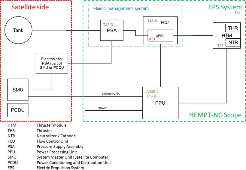
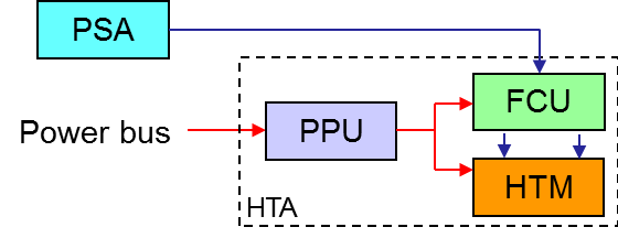
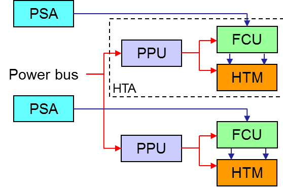
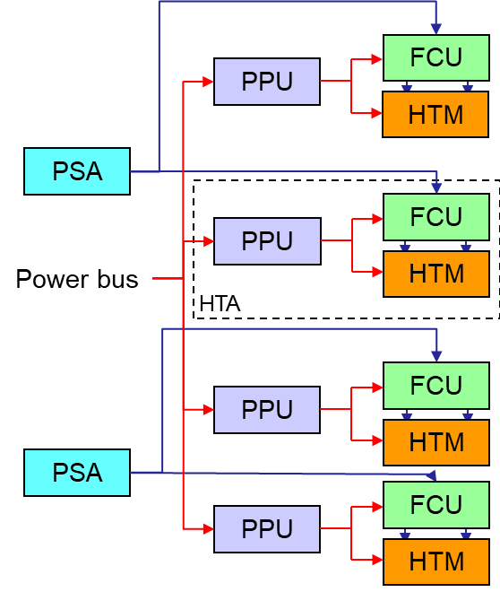
The constituents of a HTA are indicated in the diagram above. The overall strategy is to have one PPU per HTM + FCU. For the case of needed redundancy a duplication of one HTA excluding PSA is anticipated. This should enable to have a minimum complex PPU and will allow to reduce the effort for the spare PPUs.
For the FCU today a novel FCU based on fluid SMD and digital actuated valves is considered. This should enable the manufacturing of the FCU in high quantities and ensuring intechangeability without excessive testing in particular coupling testing, as all fluidic control is implementable by applying appropriate duty cycles for the used solenoid valves. Due to this a good predictability of the behaviour can be obtained and it is considered, that PPU, FCU and HTM can be manufactured and tested fully independently.
The HTA provides propulsion for orbit raising and transfer, satellite station keeping and attitude control of geo stationary satellites. For this an electric propulsion technique, based on the generation and acceleration of ions of the noble gas xenon or krypton, is used. This features a higher specific impulse compared to chemical propulsion systems. It enables orbit manoeuvres to GEO as well as SK operation in GEO at reduced propellant mass.
The HTA aims for a lean topology and design, providing a cost effective solution for commercial geo-stationary satellites. This is achieved by a modularized design of each propulsion unit (HTM) that results also in complete interchangeability.
A set of HTM can be operated from one common high voltage power supply without any switching matrix and without disconnecting the inactive devices from high voltage. Thrust control can be achieved by control of the propellant throughput only. Although this is not exploited for the actual solution, it is mentioned here to ease future discussions.
For LEO and MEO missions, usually two full branches of PSA + HTA are considered. For LEO megaconstellations, one single branch of PSA + HTA is considered.
For orbit raising of a GEO spacecraft, four branches of HTA are to be used in order to achieve failure tolerant propulsion performance. It is intended to operate 2 or 4 HTA in parallel. For station keeping of the spacecraft two branches of HTA are to be used in order to achieve single point failure free propulsion system for the spacecraft control.
The PPU/PSCU shall be used to supply the FCU and the HEMP-Thruster Module (HTM), consisting of HEMP-Thruster & Neutralizer. The PPU/PSCU will accept input power from a fixed voltage spacecraft bus and generates the stabilized voltages and currents as required by the HTM. In addition to its primary function of power generation, the PPU/PSCU shall perform the following secondary functions: telecommand, telemetry and protection. Hereinafter, the abbreviation PPU is understood as PSCU.
2. Operational Concept
- • High thrust operation / OR, where all or several available HTA branches are operated simultaneously at an operational point providing maximum thrust at a given propellant consumption (Assumption: time to orbit is critical)
- • Station Keeping operation,where one thruster is operated at the maximum available voltage to save propellant (Assumption: propellant saving is most important)
- • Graveyard / Deorbiting, where one or more thrusters at the maximum available voltage are operated to save propellant with the objective to acquire the designated graveyard orbit or to enter earth atmosphere for reentry (Assumption: propellant saving is most important).
For the HEMP-Thrusters the main control is performed by adjustment of the Propellant flow through the FCU. More in detail, thrust control is achieved by selection and switching on of the operating high voltage of the respective HTA and subsequent by commanding a desired anode current setpoint. Within the accessible safe operational area of the thruster modules, any operational voltage and current can be used as long as this is supported by the power supply. The current baseline considers the application of a lower and a higher voltage setpoint, without the necessity to have intermediate voltages (e.g 400V and 800V). The PPU high voltage converters will incorporate adequate switching circuitry to select one of the configurations. Switching is allowed only in non-energized conditions.
The FCU is not incorporating what so ever sensors for flow or pressure measurement. Accordingly the actual anode current is used as feedback signal for the flow control valve regulator. This concept has successfully already been used for the regulation of the HTA 3050 System (part of the Heinrich-Hertz-Mission).
The HTA operating modes are controlled through the PPU internal state machine / Software. It supports to either perform specific non automated activities such as venting or to automatically proceed through the operational level in automated mode.
Note, that several HTA can be activated at the same time without restrictions, as each HTA is fully independent form other branches.
3. Functional Tree
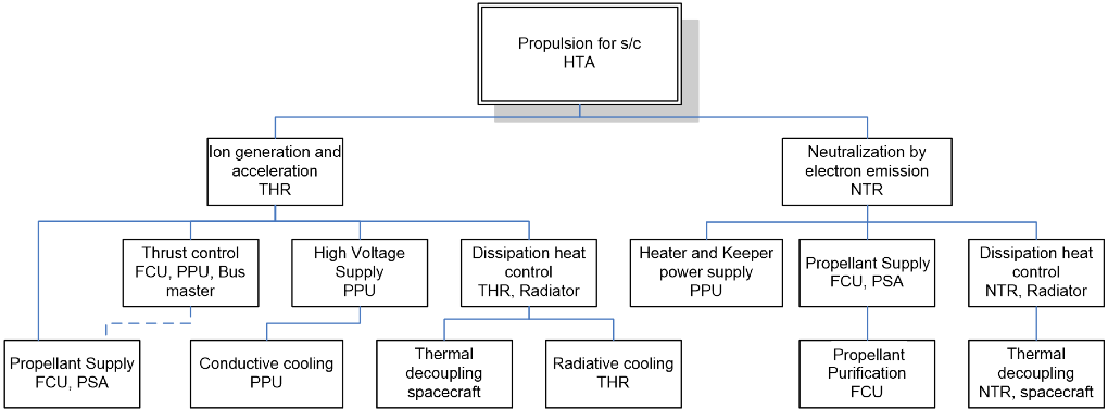
The purpose of the HTA is to provide propulsion to the spacecraft. For electrical propulsion systems this function requires the generation and electric acceleration of propellant (here xenon or krypton) ions and associated to this the compensation of the resulting spacecraft charging. Both functions are fulfilled by the HEMPT Modules. For function of the HTM propellant is fed to the HTM by means of the PSA. The Neutralizer requires purification of the Propellant (Xenon / Krypton), what is performed by the FCU.
The required electrical energy for the function of HTM is provided by the PPU. As the produced thrust is a function of the voltage and the amount of propellant provided to the thruster, the thrust can be controlled by either of these. For the HEMP-Thrusters the control is performed by adjustment of the Propellant flow through the FCU. The current drawn of the Thruster from the PPU is used as input for the control loop of the FCU. Note, that the Functions “Thrust control” and “Propellant Supply” have interdependencies (dashed line). For the thermal management of the thruster either radiation to space and thermal decoupling is needed.
The power needed for the operation of the neutralizer is provided by the NTR supplies (Neutralizer Heater / Keeper Supply) of the PPU. In addition to the functional tree above, the PPU requires thermal management via conducted cooling to the spacecraft. The FCU as stand-alone unit requires thermal and mechanical contact. It can be located either inside the spacecraft or on a mechanism boom. The surfaces of FCU are kept at a low emissivity to reduce radiative heat exchange.
4. Functional block diagram / schematic
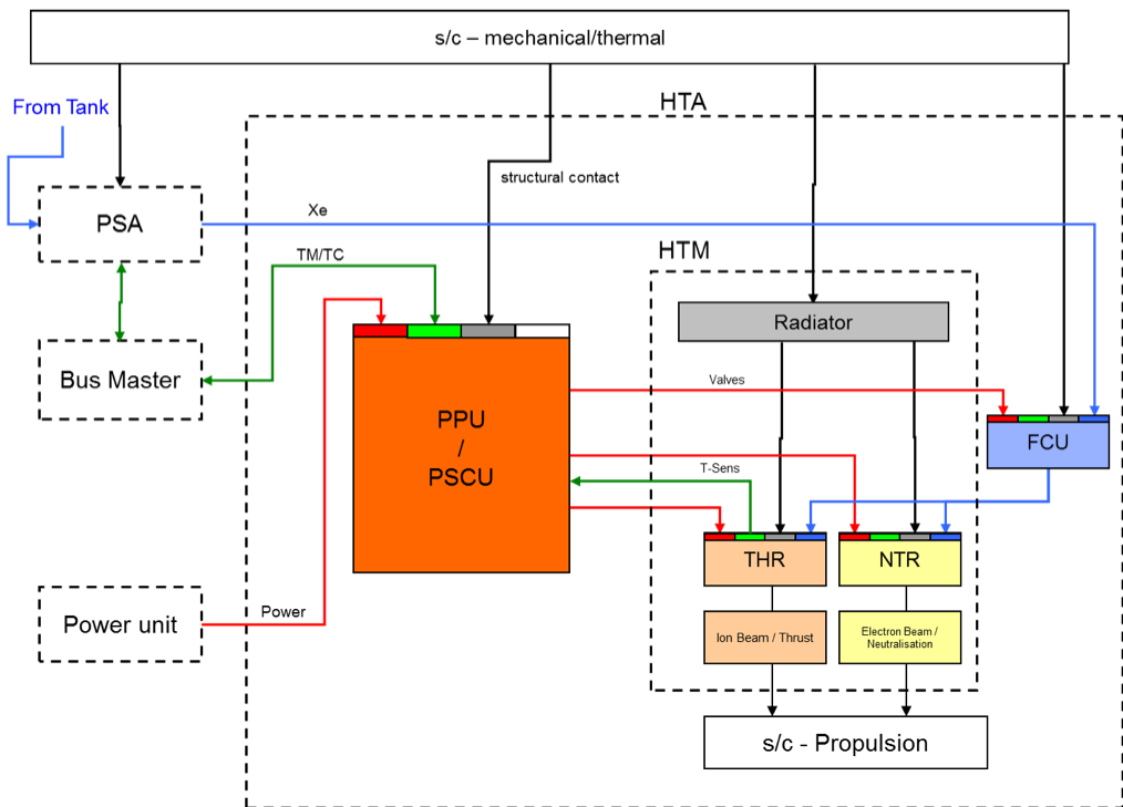
The figure above shows the function flow. The small colored rectangles on top of the boxes labeled PSCU, THR, NTR and FCU represents the different types of interfaces:
- red – indicates power function/interfaces,
- green – indicates control or sensor items;
- blue – resembles xenon / krypton propellant, and
- Black/gray – is associated with structural and thermal elements/functions.
The arrow color-code indicates the functions flow accordingly.
All power and control functionality routes through the PSCU to the HTM-components THR, NTR and FCU. The FCU distributes the propellant coming from the PSA to the HTM sub-equipment THR and NTR. The THR provides thrust, the NTR the associated neutralization. NTR and THR together provide spacecraft propulsion. The dissipated heat is handled through structural contact and thermal radiation to space environment.
Note, that thermal sensor from Thruster may be routed through the PPU to the Temperature Control System without further signal conditioning to simplify PPU. (this is considered covered with bus master)
5.Description of interfaces
As indicated in the figure the interfaces of the HTA to the spacecraft are:
- • Power from PU (Power Unit).
- • Control from the Bus Master (or any similar device)
- • Propellant Supply via PSA (Pressure Supply Assembly)
- • Structure for mechanical support, thermal contact and grounding
- • Thermal radiative coupling (not considered in the diagram)
Within the HTA, in addition interfaces between the PSCU and the individual HTMs are:
- • FCU heating, control and telemetry
- • NTR power and telemetry
- • THR power and telemetry
The external electrical interfaces of the HTA are given in the following sections:
The detailed function of the electrical interfaces is provided in the respective PPU design descriptions.
- • The bus voltage supply harness to the PPU provided by the satellite integrator via connector.
- • The Telemetry / Telecommand interfaces to the PPU. Typically, a sub-D type connector
- • PSCU grounding / bonding stud. (For EMI and PSCU protection means)
- • One (or two if required) HTM bonding stud on each HTM, to guarantee electrical contact of the HTM to spacecraft structure in order to avoid spacecraft charging and EMI.
- • The interface of the PSA valves and sensors are provided by means of flying leads. On request a specific type of connector can be provided on the end of the flying leads either only for testing purposes or in flight grade.
Currently Xenon and Krypton are considered as propellant options. The propellant supply tubing of the PSA is assumed to be welded studs. For execution of Test the studs can be equipped with screwed connectors, but are assumed to be cut prior delivery.
The tubing from the PSA to the FCU is assumed to be SS316L 1/8 inch tubing. The FCU and PSA allows direct welding to this type of tubing. The inlet studs on the HTM are compliant to this type of tubing either. For testing also here screwed connections are used, that are cut prior delivery to facilitate testing. Customers may choose to use directly screwed fittings in the low pressure part to simplify integration. Please consult Thales to discuss this if you are interested in this option.
As the FCU includes a purifier Device, the purity of the propellant provided at the FCU inlet has to be of grade 4.5 or better including any impurities that may be inside the Tank or the tubing to the FCU. Cleaning of the Tank and Tubing e.g. through evacuation is suggested. Procedures are detailed in the AIT plan to ensure minimum impurity levels. Depending on the over all mission contamination budget, purity down to 4.0 can be supported, but will drive the contamination requirements of the tank in that case. Without purifier, a grade of 5.0 or better would be needed. (not foreseen in these configurations)
6. Mechanical and Thermal architectures and interface
The individual units are mounted by flat panel mounting with screws to the spacecraft. For all HTM this interface also forms the thermal control interface. The PPU usually needs to be connected on heat pipes to be done by flat panel mounting. The HTM is designed not to require any thermal contact to the spacecraft, as it manages dissipation heat autonomously.
7. Design concepts and justifications for electrical and electro-magnetic architecture
The electrical and electro-magnetic architecture can be portioned into the following sections:
- • PPU power input
- • PPU
- • PPU output and internal harness to each HTM – grounding and CE
- • Thruster, neutralizer and space environment interaction
The PPU power input provides power to the PPU and via the PPU to the connected HTA components. It is anticipated, that there will be a high power bus connector requiring a subsequent electronic fuse / LCL. This is used to drive the HV supply.
For the remaining modules additional LCL / electronic fuses are considered for the remaining supplies and auxiliary functions.
The main contribution to electromagnetic emission is expected to originate from the high currents of the power bus interface. No significant surprises are expected here. As for most busses peak power drawn is seen as most critical element of CE, the PPU high voltage converter is specified to limit the maximum power drawn from the power bus as core function of the power supply. The high voltage supply will reduce output power in that case to protect the bus. The power drop will result in a temporary reduction of Anode voltage, but inside the engine acceptable susceptibility.
The LEO PPU is designed to operate at a power bus of 50..70V. The GEO PPU is designed to operate at a regulated power bus of 100V.
The harness connecting each HTM with the PPU consists of 2 individual cables denoted N, H; this corresponds to the functions, NTR-Harness, High-Voltage-Harness. To differentiate multiple sets the HTM number is appended. This denotes F1..F4, N1..N4, H1..H4. The connectors on PPU are the only on the Harness. In case the build in length of the HTM harness is insufficient, the harness has to be prolonged by in between harness.
For the FCU the Harness is denoted F (FCU-Harness). Connectors are foreseen on either unit (FCU and PPU to allow flexible harness routing under the responsibility of the spacecraft integrator.
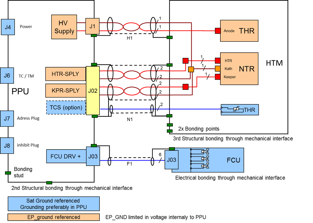
The electrical routing between PSCU and HTM considers the two Ground Systems (represented in two colors: Power_Ground indicated in blue, EP_GND indicated in red.) Shielding is connected to the connector back shell on either side.
All PPU outputs and the associated harness leading to the HTM components THR and NTR are fully differential. Each current path is conducted via shielded twisted pair wires. This minimizes the electromagnetic emission including the magnetic DC field generated by the electrical current. This applies also for the high voltage harness. On each HTM module a star point for the electric propulsion ground is located at which the different current contributions divide to the PPU supplies and the HTM loads. The electric propulsion ground is referred to within the project as EP_GND. It is the common reference potential of all NTR and THR devices within the HTA. The PPU supplies HTR Supply, Keeper Supply and Anode Supply (HV Supply) are potential free up to a certain voltage. They are protected against exceeding the isolation voltage capability by a limiting circuitry, that disables all power supplies in case the EP_GND voltage exceeds a certain threshold (see next section).
For the FCU the PPU provides three digital valve drivers. They may involve the valve impedance for forming the driver stage circuitry. This reduces the number of needed parts. The respective harness is specified to be twisted shielded pair wires to minimize electromagnetic interference.
The function of the HTM is based on the emission of charged particles. The thruster emits positively charged propellant ions with high velocity, which generates the desired thrust. The neutralizer emits electrons to compensate for the ion current of the thruster. The electrical circuit is closed as the charged particles form the exhaust plasma that is neutral in room charge. The emission currents of both devices must be equal to avoid the excessive rise of the electric propulsion ground.
Since the variation of the electric propulsion ground voltage will automatically adjust the emission of electrons to satisfy equal currents, no further special precautions are necessary. However failure cases might lead to unequal currents and exceeding of the electric propulsion ground voltage with respect to safe values for the PPU. Several protective means are implemented in the PPU to avoid damage to the PPU and the spacecraft:
- • Supervision of EP-GND voltage and automatic switch off of PPU modules
- • Limit EP-GND voltage to a maximum voltage with a dedicated circuitry.
The current emission (differential) in the THR device is not a pure DC current, but is superposed by an AC contribution. The frequencies of this AC current (typ. 300kHz + harmonics for small engines and down to 20kHz for large engines) are sufficiently low not to interfere with the telecommunication frequency bands used on telecommunication satellites. In addition a dedicated test campaign has verified that there is no interaction between the thruster plume and ion beam and the s/c antenna beam for the HTA 3050 heritage system. Possible effects of the HEMPT magnetic stray field on the co-located SPT100 Hall Effect thruster have been excluded in a dedicated test campaign in the frame of HEMP-TIS project, whereas the compatibility with a second HEMP-Thruster has been demonstrated already.
The interaction of the ion beam with the solar panels has to be considered, but is according to the use case in LEO or MEO, where the solar arrays are only visible at very high angles considered uncritical. For the case of GEO, reference is given to the HTM3050, that is designed for GEO application, meeting the necessities of that operation, where the solar arrays get in the FOV (field of view) at higher angles. For that case it is anticipated, that the evolutionary models will satisfy these application needs. During the orbit rising phase, it is expected, that due to accommodation on a mechanism, they will be sufficiently tilted not to have solar arrays in relevant angels in the FOV
For the case of radiated emission, reference to the heritage system HTM3050 tested at aerospace corporation is given (IEPC 2013-120). For the case of the LEO and GEO system, similarity is assumed for the radiative emission and susceptibility characteristics of the system. Missing gaps for susceptibility may need to be resolved on PPU level, as the susceptibility test of the heritage system was showing the absence of susceptibility.
8. Design concepts and justifications for the gas feeding system
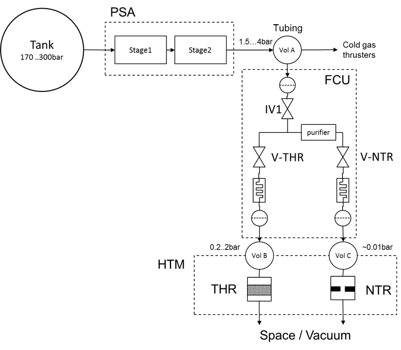
The above diagram shows the overall fluidic concept. PSA and FCU are separate units, as firstly the necessity to provide cold gas is not present on all spacecraft and secondly the required topologies, which is depending on mission and satellite size, may require different multiples of FCUs than PSAs.
For the regulation and flow control, besides the units PSA and FCU also the volumes of the interfacing tubing and parasitic volumes inside the units (including HTM) are relevant for the regulation. Accordingly the volumes of interest are denoted Vol. A, B, C.
The PSA regulates out of the tank pressure 180bar for Xenon, 300bar for Krypton to an intermediate pressure of 1.5 bar...4bar (selectable setpoint) using two regulation stages. Note, that Krypton needs to be efficiently stored at higher storage pressure. This is a consequence of the higher liquidification temperature of Krypton. Accordingly for Xenon 180 bar is sufficient, whereas for Krypton you have to allow up to 300 bar inlet pressure. A total of three serial valves are implemented to exclude single point failure (SPF) with respect to loss of isolation.
The intermediate pressure is used to feed the flow control units (FCU) and in case of cold gas availability on space craft level (optional) to supply the cold gas thrusters. The possibility to provide high flow to cold gas thrusters is the driving factor for the regulation capabilities of the PSA and the maximal ripple at low flow, as they contradict each other in the definition of sizing parameters of the PSA.
As compromise a ripple of 0.1 bar has been defined as stability criterium for the PSA. This is in line with a typical ripple load experienced in other missions. Conventional flow control units also have to cope with such ripple. Volume A will be a major influencing factor on the ripple characteristic for the pressure, whereas higher volume is beneficial for the stability of the pressure. Today a minimum of between 1 and 10 ccm is considered. A realistic volume estimate depends on the spacecraft topology. For mega constellations or if there is only one FCU per PSA, it is anticipated, that the FCU is located directly downstream the PSA. In this case the minimum volume will be applicable. For other topologies involving multiple FCU per PSA or when the FCU is located on a BOOM/ Mechanism, then the volume can be in the order of 100 ccm...500ccm depending on topology, tubing length and diameter.
The flow to the NTR device is determined by the duty cycle of the Neutralizer Valve V-NTR inside the FCU. The duty cycle is controlled in open loop as a function of the inlet pressure (through PSA telemetry). Downstream the digital valve, there is a fluidic resistance. Together with the subsequent volume C (mostly parasitic) the flow ripple is reduced.
For the control of the NTR flow ripple, the volume C has to be considered in the control of the digital valve. This parameter is controlled through HTM specification. A low volume will increase the experienced ripple. A too high volume will increase start up and depletion time when starting / stopping the neutralizer. As for the Neutralizer the minimum flow during ripple is dominantly relevant for the operation, a high ripple would require increase of the average NTR flow. Together with the subsequent volume (mostly parasitic) the flow ripple is reduced.
In this way the NTR flow can be maintained constant over all different operation points of the thruster. This is beneficial for the lifetime of the NTR, as the NTR is operated always at optimal conditions. In addition the NTR flow can be optimized with respect to operational parameters found later in orbit (that may turn out a little different to ground situation).
As protective device an Oxygen getter / gas purifier was included in the FCU in the branch to the NTR. This mitigates the risk, that traces of air / water / oxygen are present in the gas supplied to the NTR as the NTR is highly sensitive in hot state to oxygen and water. Meanwhile a hot active getter is included in the NTR to reduce the sensitivity.
The propellant supplied to the thruster is controlled by the Thruster control valve V-THR in a similar way as for the NTR. Again the duty cycle of the valve and the orifice size of the valve are determining the flow. The pulsed actuation of the valve is smoothed through the downstream flow restrictor and more dominantly by the volume between FCU and THR including the Thruster internals. The Thruster internally incorporates a ceramic flow restrictor for high voltage isolation. This element is also used to create substantial back pressure (200mbar ..2 bar) that in combination with the volume B allows to have flow ripple below 1%. A minimum of 4 ccm for the volume B has to be satisfied for this. On the high side of the volume, there is no fundamental limit, but high volume will increase the start and stop time (slope of thrust).
As the thruster current is solely dependent on the propellant flow through the thruster at constant anode voltage, the thruster current is measured and used for a closed loop regulation, eliminating the need for any flow or pressure measuring provisions. The measuring is performed within the PPU high voltage converter.
In addition this control loop eliminates any thermal dependency of the flow control valve, flow restrictors, viscosity change through temperature etc. The closed loop controller is implemented as digital regulator to reduce the amount of needed parts to the already present control circuitry (ASIC or FPGA)
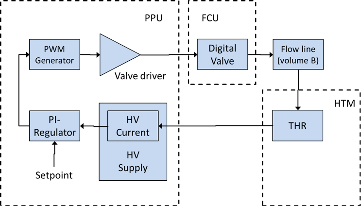
The anode current control loop is indicated in the figure above. The anode current is measured in the HV supply and filtered to eliminate higher frequency ripple from the signal. The signal is fed to the parts P, I of a PI regulator. The setpoint is subtracted from the feedback signal before it is brought to the P and I-Part. A PWM pattern generator creates out of the regulator signal a duty cycle control of the valve opening time. Then the signal is amplified by the valve driver and the V-THR is driven with that signal. The Propellant throughput is regulated by the valve and smoothed by the downstream volume. The flow results in a certain thruster current that is measured by the HV-Supply. As the choice of the regulator parameters is not obvious and as different volumes B may happen in the later application cases, the PPU will provide means to adjust the regulator parameters in a certain range.
9. Harness Design
The HTM already comes with limited harness and associated connectors. The length of this harness can be selected at the time of order between 0.25meter and 3meter. (longer tbc) This allows to directly plug the harness connectors into the PPU / PSCU. Accordingly no additional internal connectors are required for small spacecraft.
For larger spacecraft, it is anticipated, that the harness is routed over mechanical mechanism joints and will be a separate equipment As Harness is using fully standard parts no difficulty for their implementation is expected.
The design and manufacturing of the harnesses is usually in conformance to MIL standard. On request the respective parts in accordance to ESCC standards (3401, 3901) can be used instead and applied. (at extra cost) The Harness design for high voltage cable and low voltage cable considers in particular the thermal and radiation environment:
The high voltage cable is a double braided shield design providing substantial inherent shielding equivalent. This cable was tested to 100Mrad. There is the option for additional over all braided shield with >93% optical coverage. With this additional shield higher radiation dose tolerance is available. Based on this design compliance of the high voltage isolator with the radiation environment can be assumed.
For the low voltage harness an ESCC3901-19 variants are used. They already come with a very good radiation tolerance of 50Mrad. The addition of the overall braided shield provides the needed additional shielding to sustain an Orbit raising GEO mission.
Alternatively the Harness may be routed inside structures or spacecraft. In this case over all braid is not needed and can be omitted on customer request.
All Harness types are in conformance to a temperature range of -65°C … 200°C.
Parts and material have been selected also in view of ESA rules for GEO satellites. On the technical side MIL parts have given the preference where justifiable based on the intended function. (e.g. for the case of connectors, the parts usually are identical in design, materials and processes but differ in the applied screening.)
Emphasis for the parts and materials selection was on the thermal and radiation environment endurance, on cost for higher quantities and European origin.
